Computer Aided Design
Introduction
The software we will be mainly using for this topic is called Fusion 360
Here are some online resources that I use to design a number of things inside Fusion 360
Softwares used in this topic
Free softwares
- GIMP
- Inkscape
- Paint
Paid softwares
- Photoshop
- Illustrator
- Coreldraw
- Fusion 360,free for a year
2D Software
My favourite 2D software is Clip Studio Paint(CSP)
I use CSP a lot mainly to draw art in my course , additionally it also have many features similar to that of photoshop.
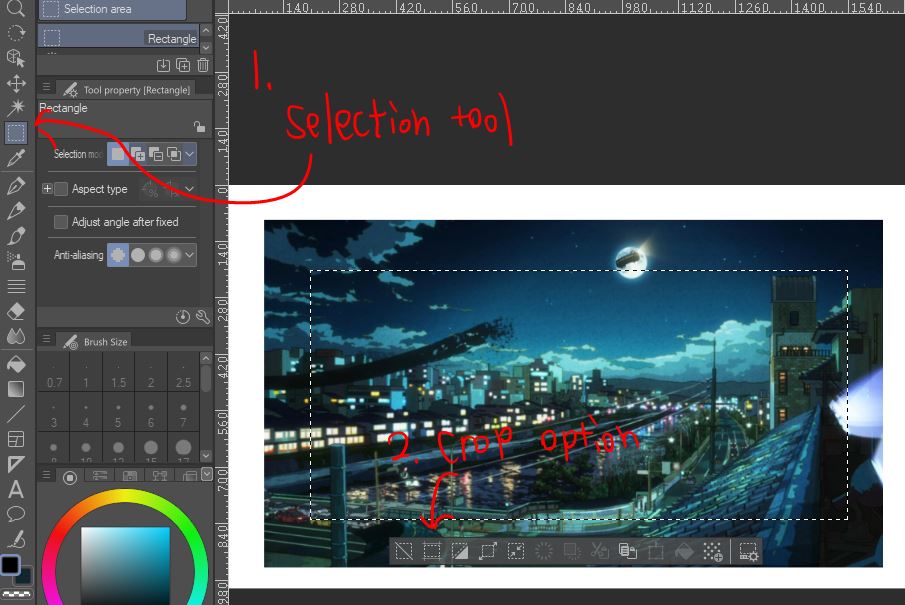
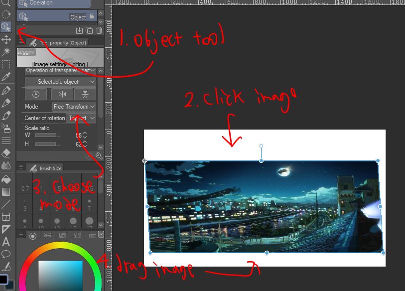
Scaling , croping and resizing photos
Scaling
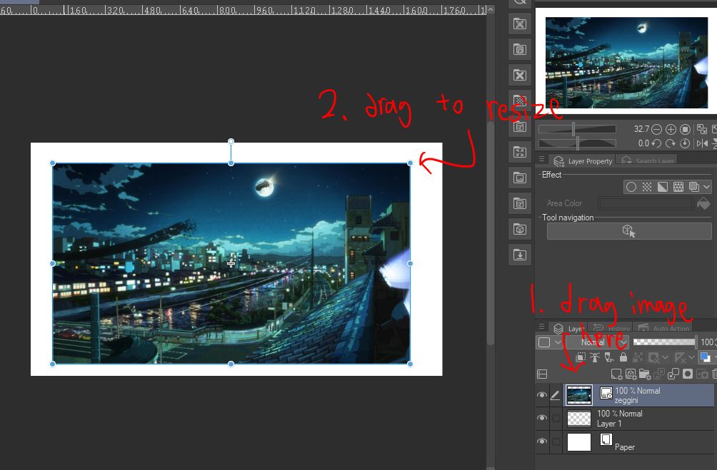
Cropping
Resizing/Free transforming
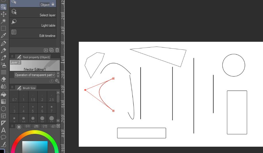
Vector lines
CSP can also generate vector lines
Mini projects using Fusion 360
To start off this new topic we used Fusion 360 to create a very simple object uing very basic methods.
The first mini project we did is a name tag
Name Tag
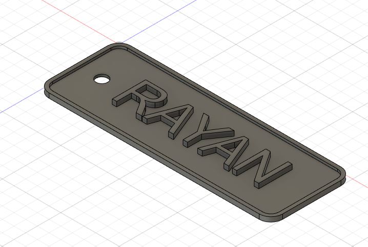
Steps
- Click on create sketch, choose a plane and create a rectangle
- Use the fillet tool to round the edges of the sketch
- Use the Extrude tool,or press E, and select the sketch
- Extrude the rectangle to the desired thickness
- Click on create sketch again , click on the top face
- drag select everything and go to modify/offset
- type in a negative value depending on thick you want the edges to be
- Finish sketch , select inner face and extrude downwards
- create sketch again and select Text, Choose font , adjust size and type in any text
- Extrude text upwards
- To make a hole , create new sketch , create a circle and downward extrude
- change operation to cut and press ok
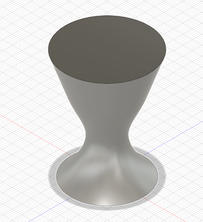
Egg Cup
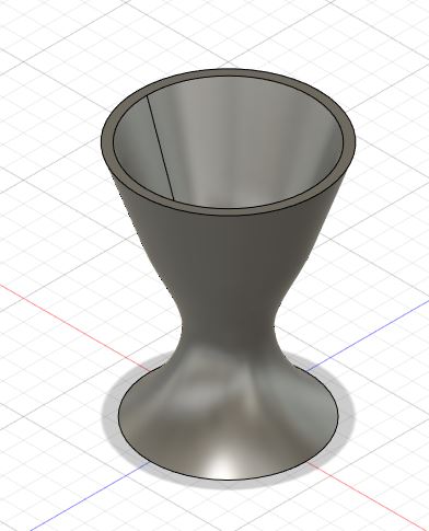
Steps
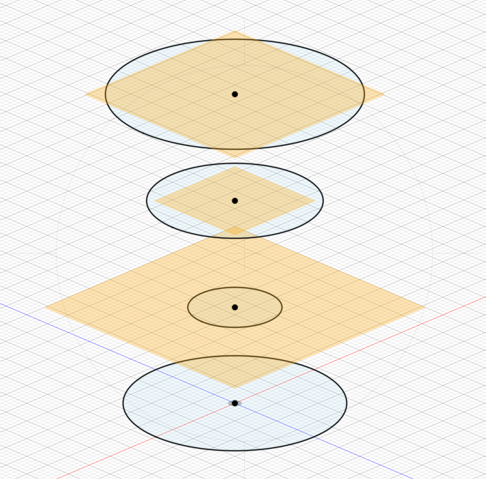
- Create sketch and select centre diam circle , plaace a circle in the origin
- choose a plane and make the diameter 38mm
- Right click on the circle and click offset plane
- move the offset circle by 18mm vertically
- Repeat step 1 to 3 but move the offset plane for circle 3 and 4 by 20mm, with diameter 30mm and 44mm respectively
- Finish sketch and select the loft tool
- Click every circle with new body as its operation
- select shell tool and click top circle
- Make the thickness 2mm and you are done
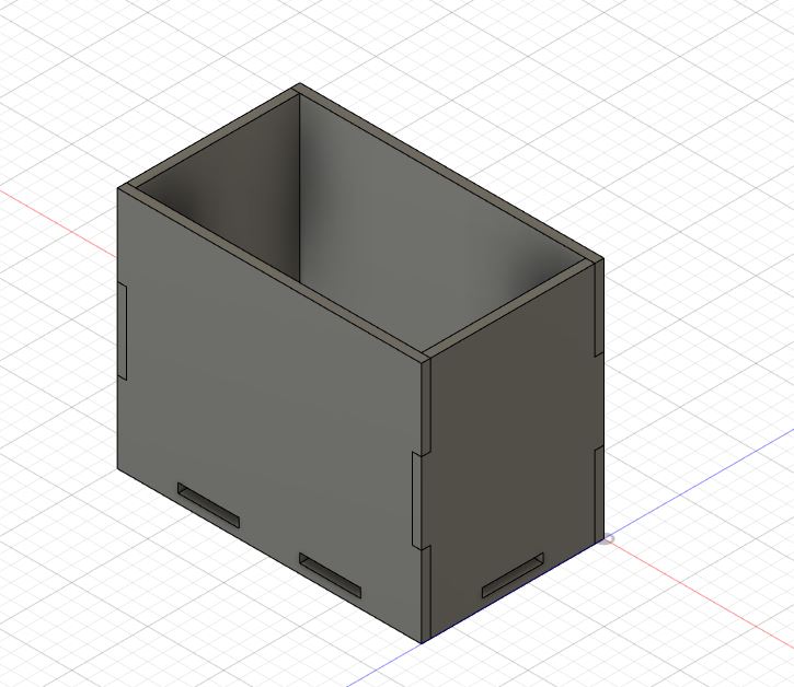
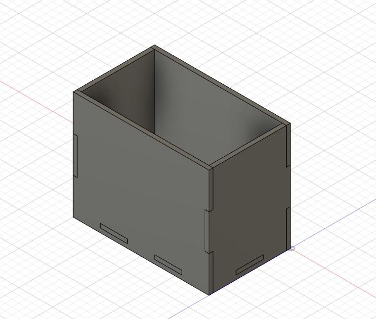
Laser cut box
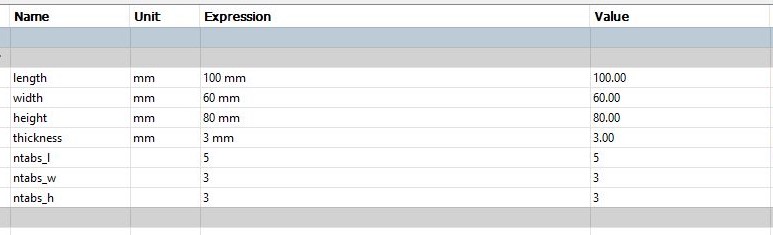
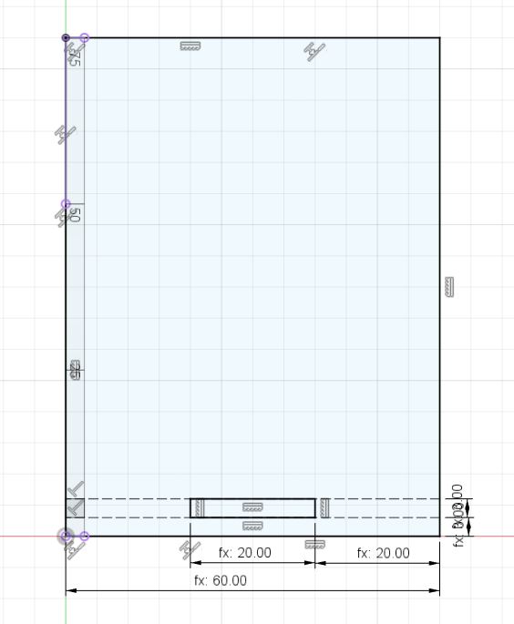
First set up parameters so that it will easier to change the dimensions of the laser cut box after modelling everything
Parameter settings can be found under modify tab
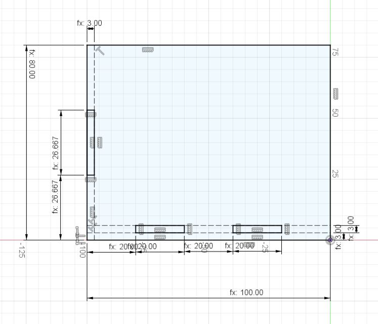
- Length: 100mm
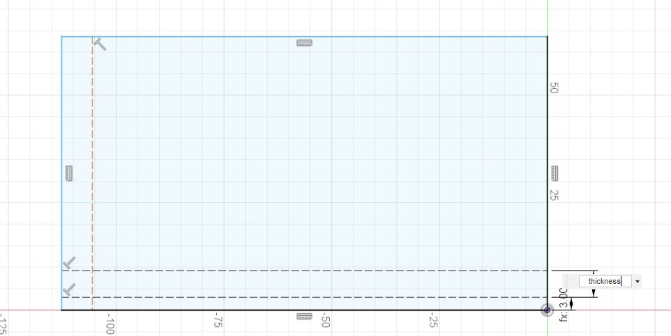
- Thickness: 3mm
- width: 60mm
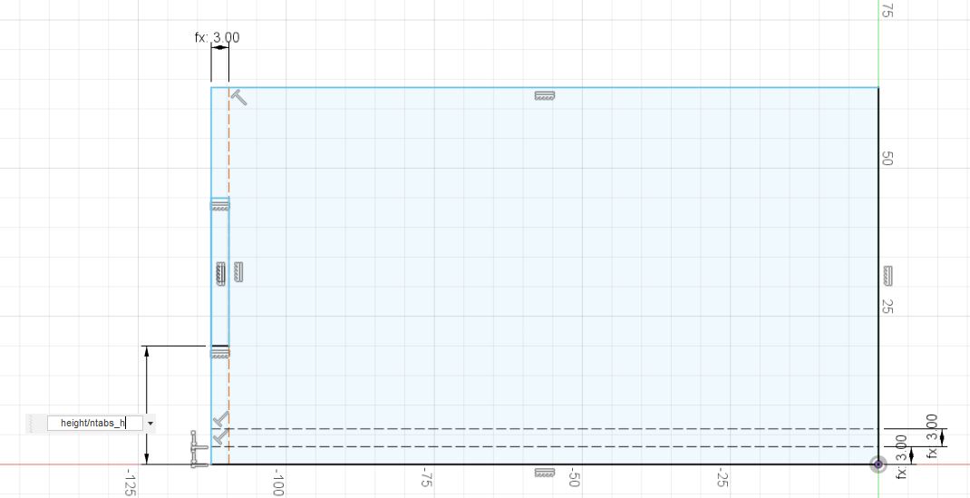
- height: 80mm
- ntabs_l: 5 units
- ntabs_w: 3 units
- ntabs_h: 3 units
note:does not have to be these exact measurments
ntab is short form for number of tabs
Steps
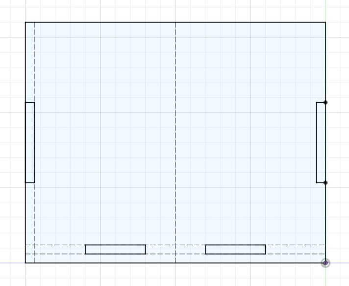
The first piece we are going to create is the Front piece
- create>new component and name it "Front"
- create sketch and choose the Y and Z axis plane
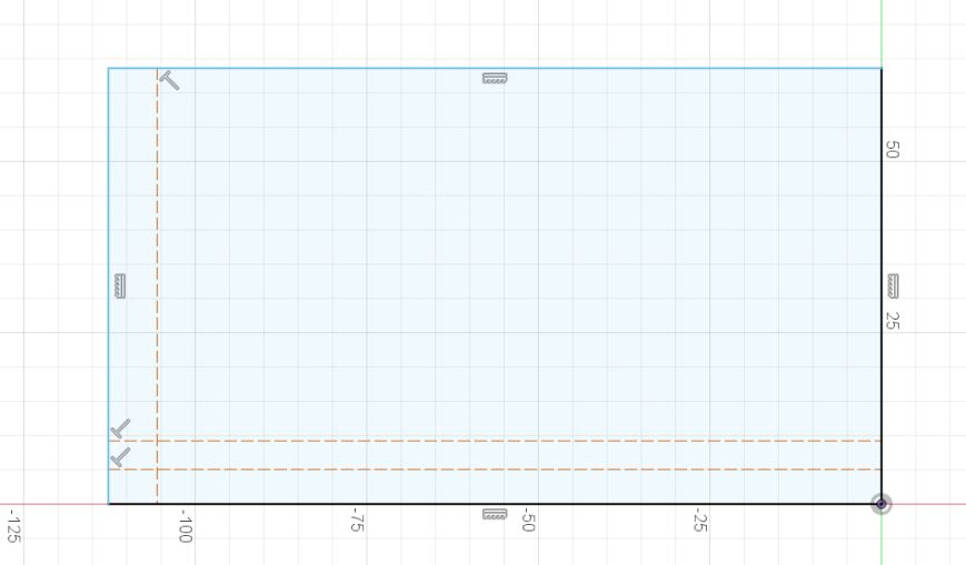
- Starting from the origin point , drag and create a 2 point rectangle of any size
- Select the line tool and turn on construction, drag and create 3 lines across the rectangle as shown below.It does not matter where you place them at this point,we will use parameters to fix the distances later.
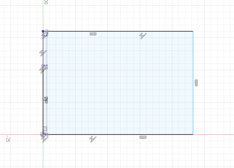
- Select sketch dimension tool and click on 2 lines to control the distance between them.
- when Fusion 360 prompts you for a measurement, type in the name of the coresponding parameter, as show above
- Input the measurements shown below
- Next draw a construction line horizontally right in the middle of the rectangle,Fusion 360 will show a triangle symbol when your cursor at the middle point.
- Select the mirror tool under the create tab
- For mirror line , select the middle line , for objects select the small rectangle to the left.
- Extrude the sketch by 3mm with operation as "new body"
- Create a new component,name it "left", and create a sketch on the left face
- Create a rectangle of any size and use the collinear tool,under constraints to fit it to the front piece
- Use the same techniques in the previous step to get the left piece as shown below
- Finish and Extrude the sketch
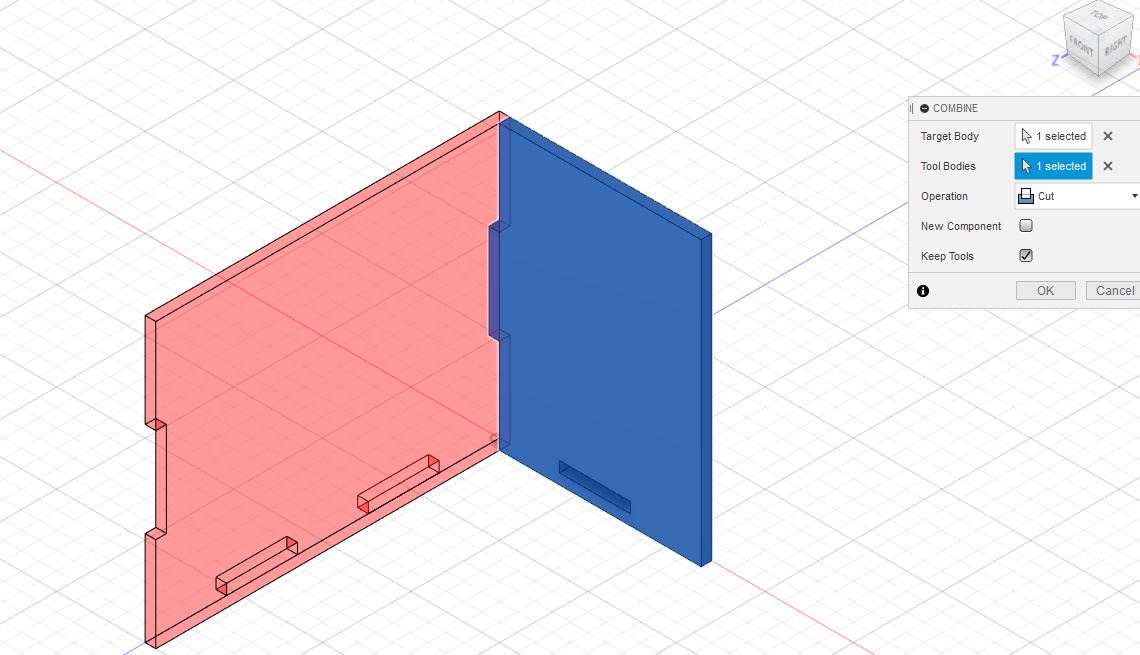
- Select the combine tool , under Modify tab
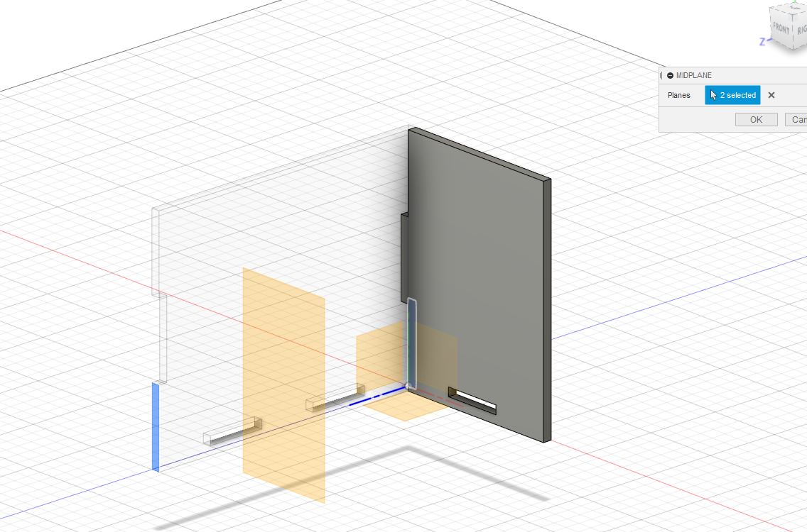
- Next under Construct tab, select mid plane and select two sides of the front piece
- Combine and cut the pieces
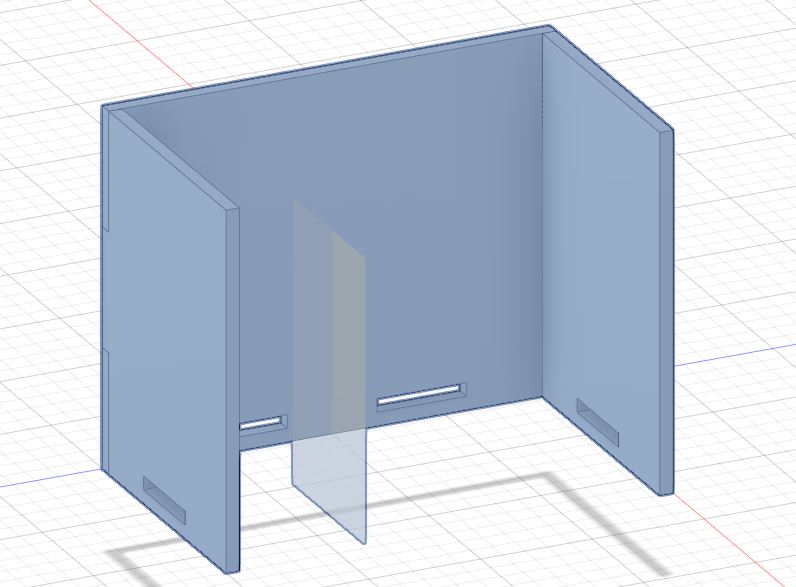
- Finally for the base piece ,Create a new component and Select the reference face for sketch
- Use the same techniques for the other faces , combine and cut
you can also use a slash symbol / , to divide the parameter , hence the function of the ntabs parameter.
Finish the sketch and you should get something like this
Target bodies: Left piece , Tool bodies: Front piece , Operation: Cut , Keep tool: Ticked , New component: unticked
Create>mirror Pattern type: Components Objects:Left piece Mirror plane: Mid plane
Repeat for the Front piece